

Why Choose Us
Professional Team
Professional R&D and production experience of connectors,Has already acquired ISO9001, ISO14001 international quality,environment and management system certificates.
Competitive Price
Our competitive pricing ensures that our customers get the best value for their money.trying to reduce costs and profits,and provide you with a good price.
Quality Control
For each process,we have strict inspection standards,and we always insist that quality is life.
Online Response
We will wait for your message within 24 hours. Thank you for your interest in our products.
What is Wire To Board
Wire-to-board connectors typically use crimp technology to allow the connection of a wire to a printed circuit board (PCB). Once the connector has been crimped to the wire, the contacts or terminals can then be inserted into the corresponding housing to complete the interconnect. Other wire-to-board connectors include IDC and SMT. Wire-to-board connectors are largely used due to their flexiblity and reliability. Greenconn's connectors can be used in low-profile designs which offer connectivity for underwater systems or systems in which space is restricted and require a more compact solution. You can count on Greenconn to always provide you a secure termination.


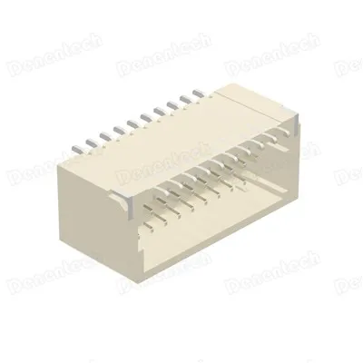
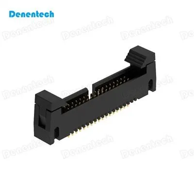


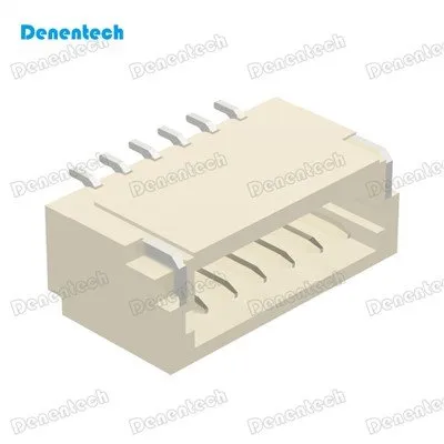
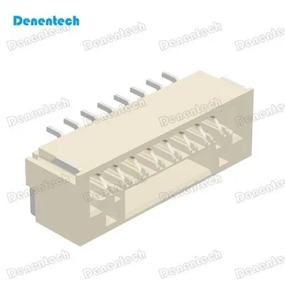


Product Categories


Benefits of Wire To Board
Compact and Space-Saving Design
Wire To Board are designed with a compact form factor, allowing for efficient use of space on the PCB. With only two pins, these connectors occupy minimal real estate, making them ideal for applications with size constraints or limited board space. Their small footprint enables designers to maximize PCB real estate and optimize the overall layout and functionality of the electronic system.
Easy and Secure Wire Termination
Wire To Board offer a straightforward and user-friendly wire termination process. These connectors typically feature screwless or push-in terminal blocks that allow for quick and easy wire insertion. The terminals securely grip the wires, ensuring a reliable and stable connection without the need for additional tools or complicated wiring procedures. This ease of wire termination simplifies assembly processes and reduces installation time.
Versatile Wire Compatibility
Wire To Board are compatible with a wide range of wire sizes and types. They can accommodate various wire gauges, from thin signal wires to thicker power cables, offering flexibility in terms of application requirements. Whether it's for low-power signals or higher current applications, these connectors provide a versatile solution for different wire types and sizes.
Secure and Reliable Connection
Despite their simplicity, Wire To Board provide a secure and reliable electrical connection. The connectors feature robust housing materials and terminal designs that ensure proper contact and minimize the risk of accidental disconnection. This reliability is crucial in applications where uninterrupted signal transmission or power delivery is essential for system performance.
Automotive
Wire to board connectors are widely used in the automotive industry for connecting a variety of automotive components, such as sensors, actuators, headlights, and taillights.
Consumer electronics
In consumer electronics, wire to board connectors are commonly used for connecting components within cameras, smartphones, and tablets.
Industrial equipment
Wire to board connectors are used in industrial equipment applications where reliable and secure connections are required, such as in the assembly of control panels, conveyor systems, and packaging machinery.
Medical devices
Medical devices often use wire to board connectors to connect a variety of sensors and other components.
Aerospace and defense
In the aerospace and defense industry, wire to board connectors are used to connect various components within aircraft and military vehicles.
Home appliances
Wire to board connectors are used in a variety of home appliances, such as washing machines, refrigerators, and ovens, to connect sensors, displays, and other components.
Types of Wire To Board
Wafer Connectors
While very similar to headers, wafer connectors offer a more suitable option to better connect a wire to a PCB. Male connectors are attached to the PCB while female connectors are crimped to the wire. Because of this, no soldering is required for the female connector. Wafer connectors are also polarized making it impossible to incorrectly plug in the mating connector during the connection process. Another advantage of wafer connectors is that they are offered in the same pitches as headers making these two connectors entirely compatible with one another.
Ejector Headers
Greenconn's ejector headers are connectors that provide an ejector mechanism for easy connects and disconnects. These connectors are also polarized making it impossible to incorrectly plug in the mating connector during the connection process.
FPC/FFC Connectors
FPC (Flexible Printed Curcuit) or FFC (Flexible Flat Cable) Connectors are cables that closely resemble a ribbon and are typically made of a flexible plastic or film with a metallic connector at the end. This type of connector offers a high level of signal reliability, compact design, with a wide variety of size and cable options.
IDC Connectors
Insulation Displacement Contact Systems (IDC) are connectors designed with sharpened blades that strip the insulation of a cable during the connection process. By doing this, individual cables no longer need to be cut, striped and crimped before connecting which greatly reduces overall processing time.
RAST IDC
RAST stands for Raster Anschluss Steck Technik and is the industry standard for home appliances. RAST is typically followed by a numerical value which represents the contact centerline spacing (in millimeters) of a specific RAST connector. For example, RAST 2.50 has a 2.50mm pitch.
What Is The Difference Between Board-To-Board, Wire-To-Board And Wire-To-Wire Connectors?
Board to board connector
The board-to-board connector is called the board-to-board connector. It is the most powerful connector product among all connector types. At present, the main spacing of board-to-board connectors is 0.4mm and 0.5mm. 0.635mm, 0.8mm, 1.00m, 1.27mm. Board-to-board connectors are mainly used in power systems, communication networks, financial manufacturing, industrial automation, medical equipment, office equipment, smart appliances, military manufacturing and other industries.
Wire-to-board connector
The so-called wire-to-board connector is the connector that connects the wires and the circuit board. The function of the connector is mainly to transmit power and signals. Therefore, the wire-to-board connector can be said to be the ancestor of all the linkers, according to various purposes and requirements. Different types of wire-to-board are numerous, but in the information industry, most of them are distinguished by the distance between the pins and the current and the voltage transmitted. The main application areas of wire-to-board connector products include commercial electronic equipment, household appliances and other general industrial and commercial fields using auxiliary circuits.
Wire-to-wire connector
The wire-to-wire connector includes a wire-to-pair cable or a cable-to-cable cable, and is characterized in that two single-wire individuals or two of the two cables are permanently connected to each other. These permanent connections are more commonly found in fixed connection center-to-wire connections and IDC connections. Wire-to-wire connector products are mainly used in automotive, communications, consumer electronics, data processing, industrial machinery and other fields.
Process of Wire To Board
Cut and strip the wire: First, the wire must be cut to the appropriate length and stripped of its insulation. This can be done using wire cutters and strippers.
Preparing the terminal: The terminal on the board must be prepared by removing any excess solder or debris. This can be done using a soldering iron and a flux cleaner.
Tinning the wire: The wire must be tinned by applying solder to the exposed metal strands. This will help to create a strong electrical connection.
Inserting the wire: The tinned wire is then inserted into the terminal on the board, making sure that the correct polarity is observed.
Securing the wire: The wire is then secured in place by soldering it to the terminal. Excess solder and flux are removed using a flux cleaner.
Insulating the connection: Once the wire is securely attached to the terminal, the connection must be insulated to prevent any accidental short circuits. This can be done using heat shrink tubing or insulating tape.
Testing the connection: Finally, the connection is tested to ensure that it is functioning correctly. This can be done using a multimeter or other electrical testing equipment.
Maintenance Tips for Wire To Board
Clean regularly
Dirt, dust, and debris can accumulate on wire to board connectors over time, which can cause connection issues or corrosion. Wiping the connectors down with a dry cloth regularly can help prevent this.
Avoid bending or twisting wires
Excessive bending or twisting of wires can cause damage to both the wire and the connector. It is important to handle wires carefully and avoid placing undue stress on the connectors.
Use the correct wire gauge
Using wires that are too thin or too thick for the connector can cause connection issues. Always use the correct wire gauge for the connector to ensure a strong and secure connection.
Check for damage
Regularly inspect the connectors for any signs of damage, such as cracks, bent pins, or corrosion. If damage is found, replace the connectors immediately.
Use proper tools
When crimping or soldering wires to the connectors, always use the correct tools and techniques. Incorrect crimping or soldering can cause connection issues or damage to the connector.
Store properly
When not in use, store wire to board connectors in a clean, dry place. Avoid exposing them to extreme temperatures or humidity, which can cause damage or corrosion.
Our Factory
Denentech Electronic Technology Co, ltd, established in 2003, Professional R&D and production experience of connectors. Has more than 3000 square meters. Specializes in manufacturer percision board to board.Wire to board connectors and cable, assemblies for connectors, for computer&perpheral devices.


Certificate

FAQ
Q: What is wire-to-board connection?
Q: What are the advantages of wire-to-board connection?
Q: What types of connectors are used for wire-to-board connection?
Q: What factors should be considered when selecting wire-to-board connectors?
Q: How is wire-to-board connection made?
Q: What is a pitch in wire-to-board connectors?
Q: What is the difference between vertical and right-angle wire-to-board connectors?
Q: What is the best way to attach wire to PCB?
Q: What is a connector on a PCB board?
Q: How do I choose a PCB connector?
Q: What is the line spacing for PCB?
Q: What are Benefits of Wire-to-Board Connectors?
Q: What should be considered when selecting a wire-to-board connector?
Q: Can you solder wires directly to PCB?
Q: Does PCB require soldering?
Q: What is the difference between soldering and PCB?
Q: How do I attach wires to PCB without soldering?
Q: How many times can you solder a PCB?
Q: Do you need to solder both sides of a PCB?
Q: What is an insulation displacement connector (IDC)?
We're professional wire to board manufacturers and suppliers in China, specialized in providing high quality customized products. We warmly welcome you to wholesale high quality wire to board at competitive price from our factory. Contact us for more details.
Box Header PCB Male, Single Row Right Angle DIP with Peg, Dual Row Right Angle with Peg